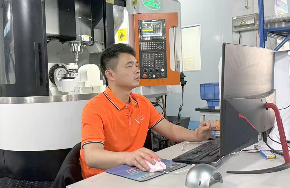
Short answer: Use 3-axis CNC machining when the required features are accessible from a small number of straightforward orientations and the datum relationships can be controlled through practical setups. Use indexed 3+2 machining when a part has several angled or multi-face features that can be machined while the rotary axes are locked. Use simultaneous 5-axis machining when the cutter must change orientation continuously to follow complex surfaces, maintain tool access or control difficult feature relationships. The correct choice is the least complex process that can produce and verify the drawing requirements reliably.
3-Axis vs 5-Axis CNC Machining at a Glance
The number of machine axes does not determine part quality by itself. Machine condition, programming, workholding, cutting tools, material behavior, process control and inspection all affect the delivered result. Axis count mainly changes how the tool and workpiece can move relative to each other.
Decision factor | 3-axis machining | Indexed 3+2 machining | Simultaneous 5-axis machining |
|---|---|---|---|
Basic motion | Linear movement in X, Y and Z | X, Y and Z cutting after two rotary axes position the part | Linear and rotary axes can move together during cutting |
Best suited to | Accessible faces, pockets, plates, brackets and straightforward housings | Multi-face parts, compound-angle holes and features needing several fixed orientations | Freeform surfaces, impellers, difficult undercuts and continuously changing tool orientation |
Setups | May require manual repositioning for additional faces | Can machine several orientations in one fixture | Can combine complex access and continuous contouring in one strategy |
Programming | Usually simpler | More planning for indexed orientations and collision control | Highest programming, simulation and verification demand |
Tool access | Limited by spindle direction and each setup | Improved through indexed part orientation | Greatest flexibility where continuous orientation is justified |
Cost tendency | Often efficient for simple geometry | Can reduce setup labor and datum-transfer risk | Can be economical for suitable complexity but unnecessary for simple parts |
Inspection challenge | Usually straightforward when datums remain accessible | Multi-face relationships need a clear datum and inspection plan | Complex surfaces and relationships may require CMM programming or profile evaluation |
This table is a starting point, not an automatic routing rule. A skilled supplier can sometimes produce a complex-looking component efficiently on a 3-axis machine with well-designed fixtures. A visually simple part can require multi-axis planning if critical features lie on several orientations and must relate closely to one datum system.
Use VOGUC’s CNC machining resource center for the related tolerance, cost, RFQ and lead-time decisions, and review the complete CNC machining capabilities when the question moves from process education to supplier fit.
What 3-Axis CNC Machining Means
A 3-axis milling machine moves the cutter relative to the workpiece along three linear directions: X, Y and Z. The workpiece is clamped in a fixed orientation during each operation. The machine can create faces, holes, pockets, slots, bores, threads and contours that the cutter can reach from that orientation.
Typical 3-axis parts include:
flat plates and mounting bases;
brackets with accessible pockets and hole patterns;
enclosures machined from the top and then turned for secondary faces;
fixtures, jigs and tooling blocks;
heat sinks and electronic housings;
parts whose side features can be completed in one or two additional setups.
Three-axis machining is not “low precision.” With an appropriate machine, fixture, toolpath and inspection plan, it can produce demanding CNC parts. Its limitation is access. When a feature points away from the spindle, the part must usually be repositioned, held in another fixture or machined with specialized tooling.
Each repositioning creates work. The operator must locate the part, establish the new work coordinate, protect already-machined surfaces and ensure the next operation remains related to the correct datums. This can be completely acceptable. The question is whether the number of transfers and their associated risk are still practical for the drawing.
What 5-Axis CNC Machining Means
A 5-axis machine adds two rotary axes to the three linear axes. Depending on machine design, the table may tilt or rotate, the spindle head may move, or the machine may combine those arrangements. The extra motion allows the cutter to approach a part from more directions. Autodesk's current five-axis machining overview likewise distinguishes three linear axes from two rotational axes and separates positional 3+2 strategies from simultaneous motion.
*Multi-axis equipment increases access, but the process still depends on fixture design, program verification and drawing-led inspection planning.*
Five-axis capability can help when a component includes:
features on several faces that should remain in one controlled setup;
holes or bores at compound angles;
contoured or freeform surfaces;
deep features where tilting enables a shorter, more rigid tool;
critical positional or profile relationships across different orientations;
geometry where conventional tool access creates collision or reach problems.
The process is valuable because it can reduce manual setups, improve access and keep important feature relationships tied to one workholding strategy. It should not be selected merely because the machine is more advanced. Extra programming, simulation, machine time and inspection planning must deliver a real manufacturing advantage.
Indexed 3+2 vs Simultaneous 5-Axis Machining
The phrase “5-axis machining” is often used for two different strategies. Buyers do not always need to specify which one, but understanding the distinction helps when reviewing a quotation.
Indexed 3+2 machining
In indexed 3+2 machining, the two rotary axes position the workpiece at a selected angle. Those rotary axes then remain locked while cutting takes place using X, Y and Z motion. The machine can index to another orientation and repeat the process without the operator manually reclamping the part. This matches Autodesk's current 3+2 clearing documentation, which states that the rotary axes move to selected angles and remain locked during cutting moves.
This approach is useful for multi-face parts, angled holes and planar features located at different orientations. It can reduce setup count while keeping toolpaths comparatively straightforward. A part with five accessible faces or several compound-angle ports may benefit from 3+2 even if it has no freeform surface.
Five-sided machining is not the same as simultaneous 5-axis machining. A five-axis machine may expose five sides of a prismatic part through indexed 3+2 positions while cutting each side with fixed rotary axes. Haas describes the same distinction between five-sided 3+2 positioning and simultaneous 5-axis contouring. Buyers should therefore ask which motion strategy the quoted route uses instead of treating every part made on a five-axis machine as a simultaneous five-axis part.
Simultaneous 5-axis machining
In simultaneous machining, the linear and rotary axes can move together while the cutter is engaged. The tool orientation changes continuously along the path. This is useful for complex contours, turbine or impeller-style geometry, deep sculpted surfaces and situations where the tool must maintain a controlled angle to the surface.
Simultaneous motion introduces additional planning. The programmer must manage tool-center-point control, kinematics, axis travel, collision risk, rotary limits, workholding clearance and surface transitions. Simulation and prove-out become especially important. For a part made only of flats, pockets and fixed-angle holes, simultaneous motion may add no meaningful benefit over indexed 3+2 machining.
Setup Count Is Often the Real Decision
Buyers sometimes compare machines when they should compare manufacturing plans. A drawing is not improved merely by attaching the words “5-axis required.” The engineering question is how many stable setups are needed and what happens to critical relationships when the part moves between them.
Imagine a housing with a precision bore on the top face and two cross holes on opposite sides. A 3-axis route might machine the top, then transfer the part to fixtures for each side. If the cross-hole positions have generous tolerances, this can be economical and reliable. If all three features have tight true-position requirements relative to a common datum system, a multi-axis setup may reduce datum-transfer risk.
Fewer setups can provide several benefits:
less manual loading and alignment;
fewer opportunities to damage finished surfaces;
fewer fixture interfaces and coordinate transfers;
better access to several faces from one datum establishment;
shorter queue and handling time between operations.
However, fewer is not always better. A dedicated secondary fixture can be very stable and efficient for repeat production. Separating roughing from finishing can help manage distortion. A large part may need repositioning because of machine travel or fixture access. Process choice must consider the full route rather than setup count alone.
“One setup” also does not mean “one operation.” The part may remain in one fixture while the program uses several indexed positions, tools, work offsets, probing cycles, roughing and finishing stages. The meaningful sourcing question is whether the proposed route preserves the required datum relationships and controls risk—not whether the quotation uses the smallest possible operation count.
When 5-Axis Machining Creates Real Value
Multi-face geometry with shared datum relationships
Parts used in robotics, automation, medical equipment, aerospace-style structures and fluid systems often place holes, ports, sealing faces or mounting features on several orientations. Keeping these features within one indexed setup can reduce the error introduced by repeated locating.
Compound angles and difficult access
A hole that is angled in two planes may be awkward to fixture on a conventional machine. A tilting rotary table can orient the feature directly toward the spindle. The same principle helps with chamfers, ports and surfaces that would otherwise need custom angle fixtures.
Shorter tools for deep or steep features
Tilting the part or tool can improve access so that a shorter cutter reaches the surface. Shorter tools are generally more rigid and can reduce deflection and vibration. The actual benefit depends on cavity shape, holder clearance, material and finish requirements.
Freeform or contoured surfaces
Continuous tool orientation can help maintain an effective cutting position on complex surfaces. It can also reduce the need for extremely long tools or multiple blended operations. Surface quality still depends on cutter geometry, step-over, machine motion and finishing strategy.
Consolidation of an otherwise risky route
If a 3-axis plan requires many custom fixtures, several coordinate transfers and repeated inspection between operations, a multi-axis route may reduce total manufacturing risk even when the machine's hourly cost is higher.
When 3-Axis Machining Is the Better Choice
A responsible supplier should also identify when 5-axis machining is unnecessary.
Three-axis machining is often the better route when:
all critical features are accessible from one or two simple directions;
the part is a plate, block, bracket or housing with straightforward geometry;
secondary faces have practical tolerances and stable fixturing;
repeat quantities justify a dedicated fixture;
the part size, stock form or workholding does not suit the available 5-axis machine;
multi-axis programming and prove-out would add cost without reducing risk;
the required feature can be made more reliably with a standard boring, drilling or milling setup.
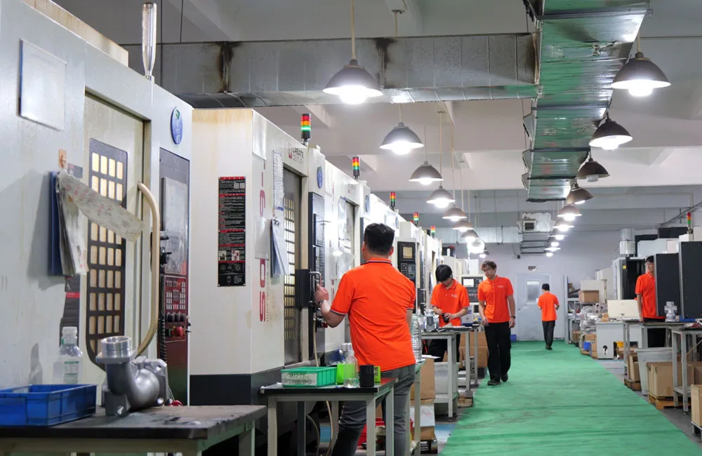
*A capable supplier routes each part to suitable equipment rather than assuming that the highest axis count is always the best option.*
For example, a rectangular aluminum plate with top-side pockets and a few through holes does not normally need 5-axis machining. A bracket that requires one additional side operation may still be more economical on 3-axis equipment. If the quote specifies 5-axis for such a part, ask what setup, access or tolerance problem the process solves.
Does 5-Axis Machining Produce Better Tolerances?
Not automatically. Five-axis machining can improve certain feature relationships by reducing reclamping, but axis count is not a tolerance guarantee. Accuracy depends on machine calibration, rotary-axis condition, thermal behavior, probing, workholding, cutting force, tool deflection, material stability and inspection uncertainty. ISO 10791-6, for example, defines kinematic tests for machining centres with linear and rotary axes; those machine tests are useful context but are not a substitute for validating the finished part against its drawing.
A drawing may contain a tight positional requirement between features on different faces. Producing them in one multi-axis setup can reduce one source of transfer error. Yet if the fixture is unstable, the tool is too long or the rotary center is not controlled, the result can still fail.
VOGUC states that critical dimensions may reach ±0.01 mm after engineering review. This is not a blanket tolerance for every 5-axis feature. Part size, geometry, wall thickness, material, heat treatment, surface treatment, datum strategy and measurement access must be evaluated. Buyers should specify functional tolerances and allow the supplier to propose the route.
For broader tolerance planning, see the CNC machining tolerance guide.
Surface Finish and Tool Orientation
Five-axis motion can improve tool orientation on contoured surfaces. Keeping the cutter in a favorable contact region can reduce tool reach and help maintain consistent cutting conditions. It may also allow a ball-end mill or other cutter to avoid an ineffective contact point.
This does not mean every five-axis part has a better finish. Scallop height, step-over, feed, speed, tool wear, vibration, machine dynamics and finishing allowance still matter. Indexed transitions can leave witness marks if operations are not blended. Simultaneous motion can show surface variation if rotary-axis movement is not smooth enough for the requirement.
Cosmetic surfaces should be identified on the drawing or supporting specification. State whether tool marks are acceptable, define the required roughness where function demands it and provide appearance standards for visible surfaces. Do not rely on a photograph alone to define an engineering finish.
Cost and Lead-Time Comparison
Five-axis equipment usually carries higher machine, programming and verification costs, but the total part cost can still be lower when it removes fixtures, setups, long-reach tooling, handling or rework risk. Conversely, a simple component can cost more if it is forced onto a multi-axis route without a real benefit.
Cost or schedule factor | What can favor 3-axis | What can favor 5-axis |
|---|---|---|
Programming | Simple geometry and standard operations | Complex route can be consolidated into one coordinated program |
Fixturing | Stable standard vise or dedicated repeat fixture | Avoids several custom angle fixtures or manual transfers |
Machine time | Short, direct cuts on accessible features | Better access can shorten tools or reduce air cutting and repositioning |
Setup labor | One or two simple operations | Many orientations can be indexed in one fixture |
Inspection | Accessible datums and independent features | Multi-face relationships benefit from one datum strategy |
Risk | Proven simple route with controlled secondary setups | Fewer transfers reduce cumulative location or handling risk |
Quantity matters. A one-off prototype may benefit from flexible multi-axis access because making several dedicated fixtures is inefficient. For repeat production, a stable 3-axis fixture can spread its cost across the batch. The supplier should evaluate both immediate quantity and expected repeat demand.
The complete quotation should also account for material, finish, tolerance, inspection, packaging and delivery scope. The CNC machining cost guide explains how these factors interact.
Inspection Planning for Multi-Axis Parts
The inspection plan must follow the drawing's datum structure, not the machine setup alone. A part can be made in one fixture and still require careful alignment during measurement.
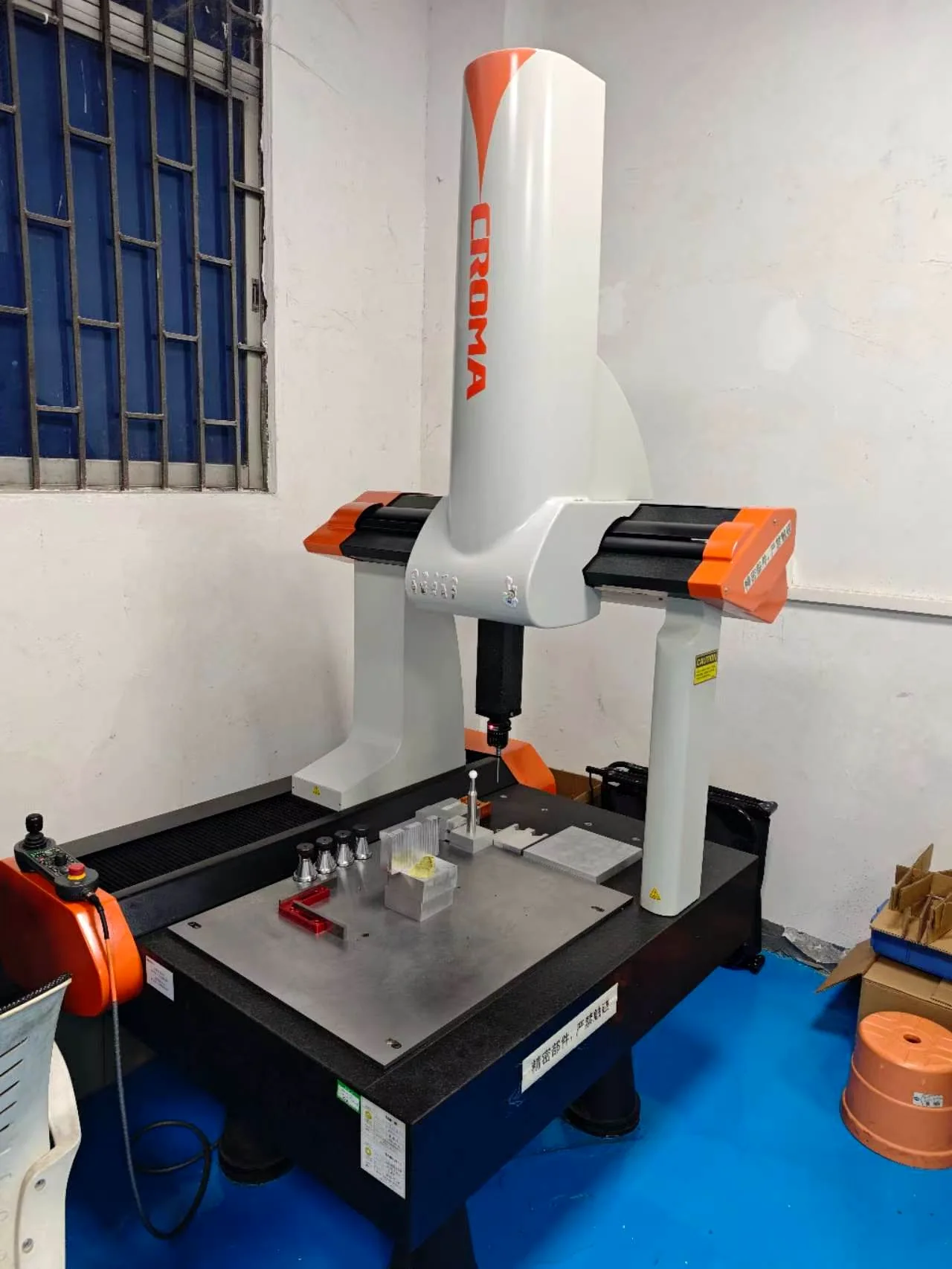
*Complex multi-face relationships may be verified with a 3D CMM when feature geometry, tolerance and access make that method suitable.*
A 3D CMM can evaluate coordinate relationships, feature position and complex geometry. A 2.5D vision system, height gauge or functional gauge may suit other features. No instrument is automatically correct for every dimension.
For a multi-axis RFQ, buyers should clarify:
which datums control the critical multi-face relationships;
whether profile or positional tolerances apply;
which characteristics need actual-value reporting;
whether a ballooned drawing and full dimensional report are required;
the inspection sample quantity;
whether first-article approval is needed before the remaining batch proceeds.
The supplier should review whether the part can be inspected in the same condition in which it functions. Thin walls, flexible features, surface finish and clamping force can affect both machining and measurement.
Geometry Examples: Choosing the Practical Route
Example 1: Flat electronics mounting plate
The part has top-side pockets, tapped holes and an outside profile. All important features are accessible from the top, and the bottom only needs facing. A two-operation 3-axis route is likely appropriate. Five-axis motion would not solve a meaningful problem.
Example 2: Manifold with ports on five faces
The body includes cross-drilled passages and sealing ports on several orientations. The positions relate to common datums. Indexed 3+2 machining may reduce transfers and allow the ports to be completed from one fixture. Simultaneous motion may not be necessary because each port is machined at a fixed angle.
Example 3: Sculpted medical-device component
The component includes a curved functional surface and difficult tool access. Continuous orientation may allow shorter tools and a more consistent contact angle. Simultaneous 5-axis machining can be justified if the surface and access cannot be produced reliably through indexed operations.
Example 4: Repeat-production bracket
The bracket needs machining on three orthogonal faces, but tolerances are practical and volume supports dedicated fixturing. A proven 3-axis production route may outperform a flexible 5-axis route on cost and throughput. The decision should be based on total process capability, not visual complexity.
What Buyers Should Send for an Accurate RFQ
Do not decide the process from a screenshot. Send enough information for the supplier to compare routes.
A STEP, STP, X_T or another agreed 3D model containing complete geometry.
A controlled 2D drawing with revision, datums, GD&T, threads and critical dimensions.
Material grade and condition, including any heat-treatment requirement.
Prototype and expected repeat quantities.
Surface finish, coating and cosmetic-surface requirements.
Mating-part, assembly or functional information where it affects datums or access.
Required inspection reports, certificates and sample quantity.
Delivery destination and required timing.
Unsure whether your part needs 3-axis, 3+2 or simultaneous 5-axis machining? Send the model and drawing to VOGUC. The engineering review will compare access, setup count, datum transfer, tolerance and inspection risk before the quotation route is confirmed.
Avoid writing “must be 5-axis” unless the process itself is a controlled customer requirement. If performance is what matters, define the geometry, tolerance, finish and evidence. This gives the supplier room to propose the most economical stable process.
What the supplier should return with the quotation
A useful quotation should do more than name a machine type. For a part whose route materially affects cost or risk, ask the supplier to state:
the proposed process: 3-axis, indexed 3+2, simultaneous 5-axis or a combined route;
the expected number of physical reclampings, not only the number of programmed operations;
which critical features remain tied to the same datum establishment;
any inaccessible, high-risk or long-reach features found during review;
whether special fixtures, soft jaws or inspection programming are included, reusable or charged separately;
the planned inspection method for the drawing's critical characteristics;
assumptions that could change price or lead time after engineering review.
These answers make competing quotations more comparable. A lower unit price may rely on more transfers, exclude fixture or inspection scope, or assume a simpler tolerance interpretation. Conversely, a higher machine rate may be offset by fewer fixtures and less handling. The buyer should compare the complete manufacturing and verification route rather than the axis label alone.
How VOGUC Reviews 3-Axis and 5-Axis Projects
VOGUC operates 30 CNC machines in a 2,000+ m² facility and supports 3-, 4- and 5-axis milling together with CNC turning and turn-mill machining. MOQ starts at one piece. These facts describe available capacity; they do not determine the correct route for an individual drawing.
The project review considers stock form, feature access, machining envelope, setup sequence, datum transfer, tool reach, material behavior, finishing and inspection. The listed maximum milling envelope is up to 1000 × 600 × 400 mm, subject to geometry, workholding, tool access and machine-route review. Rotary tables, fixtures, clamps, stock allowance, toolholders and safe clearance reduce usable space, so a part that fits nominal travel may still exceed the practical machining envelope or require another strategy.
For complex components, the team evaluates indexed and simultaneous approaches based on what the geometry actually needs. Inspection planning may use 3D CMM, 2.5D vision measurement, height measurement or suitable gauges. Material certificates and dimensional reports can be supplied when agreed for the order.
Review the 5-axis CNC machining service for commercial project requirements or compare the broader CNC milling capability.
Frequently Asked Questions
Is 5-axis CNC machining always more accurate than 3-axis machining?
No. Five-axis machining can reduce reclamping and datum-transfer error for suitable parts, but accuracy still depends on the machine, calibration, fixture, tools, material, program and inspection method. A stable 3-axis process can be the more capable route for straightforward geometry.
What is the difference between 3+2 and simultaneous 5-axis machining?
In 3+2 machining, the rotary axes position the part and remain locked while X, Y and Z cutting occurs. In simultaneous 5-axis machining, linear and rotary axes move together during cutting. Fixed-angle multi-face features often suit 3+2; continuously changing contours may justify simultaneous motion.
Does a five-sided part require simultaneous 5-axis machining?
Usually not. A five-sided part may be completed with indexed 3+2 machining because each face is machined at a fixed orientation. Simultaneous motion is only necessary when the tool orientation needs to change continuously or access cannot be achieved through indexed positions.
Does 5-axis machining guarantee that a part is completed in one setup?
No. A five-axis machine can reduce reclamping, but fixture access, back-side features, stock removal, machine travel, tool clearance, distortion control or inspection requirements may still require another setup. Ask the supplier for the expected number of physical reclampings and how critical datum relationships will be preserved.
Is 5-axis machining always more expensive?
Its machine and programming rates can be higher, but total part cost may be lower when the process removes several fixtures, setups or risky transfers. For a simple part, 3-axis machining is often more economical. Quotations should compare the complete route.
Can 3-axis machining make complex parts?
Yes. With suitable fixtures, tools and multiple setups, 3-axis equipment can produce many complex parts. The tradeoff is setup count, access and control of relationships between orientations. Complexity alone does not prove that 5-axis machining is required.
When should I specify 5-axis machining on the drawing?
Specify the process only when it is a controlled contractual requirement. Otherwise, define the functional geometry, datums, tolerances, finish and inspection evidence, then allow the supplier to propose 3-axis, 3+2 or simultaneous machining.
Can VOGUC machine one 5-axis prototype?
VOGUC's MOQ is one piece, subject to drawing, material, geometry, finish and inspection review. Qualifying samples may be completed in as fast as three days, but actual lead time is confirmed only after the complete RFQ is evaluated.
How are multi-face 5-axis parts inspected?
The method is selected from the drawing and feature relationship. Complex datum-related geometry may use a 3D CMM, while accessible profiles, heights, threads and other features can use vision systems, height gauges or appropriate functional and dimensional gauges.
Conclusion: Choose the Simplest Route That Controls the Drawing
Three-axis machining is efficient and capable when features are accessible through practical setups. Indexed 3+2 machining adds multi-face access without requiring continuous rotary motion. Simultaneous 5-axis machining is valuable for complex contours, changing tool orientation and difficult access. None of these processes is universally superior.
The best purchasing decision is to define function, datums, tolerances, finish, quantity and inspection evidence, then compare the proposed manufacturing route. A credible supplier should explain both why 5-axis machining helps and when a simpler process is the better choice.
Review the 5-axis CNC machining service, then send your CAD files and drawing for a process review. VOGUC will evaluate whether 3-axis, indexed 3+2, simultaneous 5-axis or a combined route provides the most practical path from prototype to repeat production.
Editorial Sources and Engineering Context
These references support the process definitions and machine-performance context used in this guide. They do not select a manufacturing route or prove finished-part conformity for a specific order. The released drawing, contractual requirements, machine configuration, process plan and agreed inspection evidence control the project.