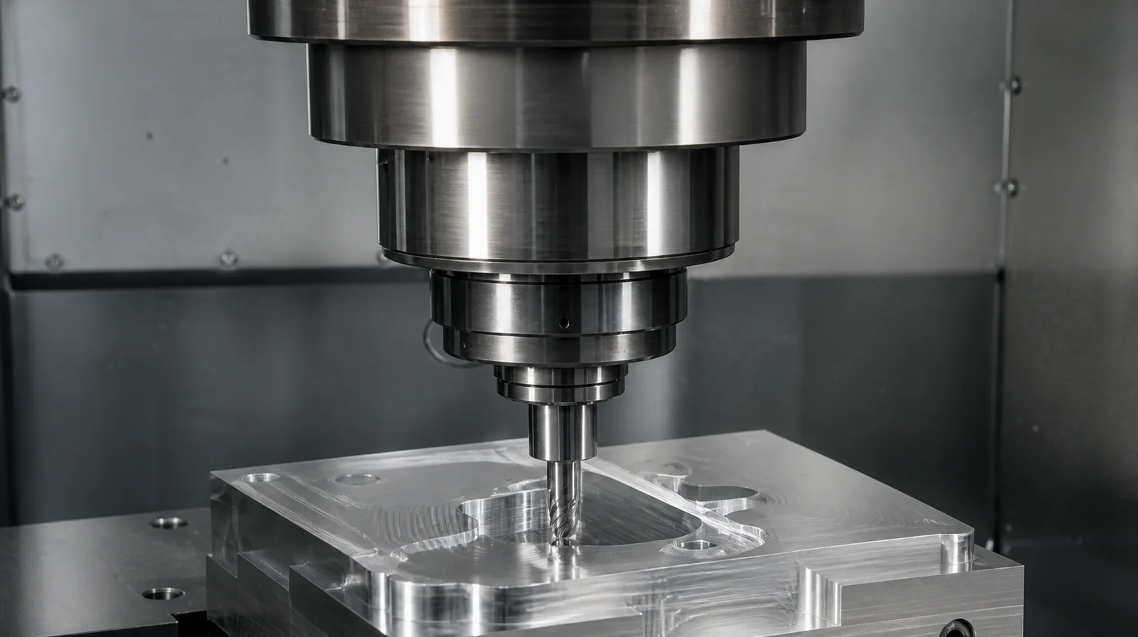
The difference between CNC milling and CNC turning is easy to describe but harder to apply to a real custom part. In milling, a rotating cutting tool removes material from a workpiece that is held in a fixture. In turning, the workpiece rotates while a cutting tool removes material, making the process naturally efficient for round geometry. Many parts contain both prismatic and rotational features, so the best manufacturing route may combine the two.
For a buyer, process selection affects price, achievable features, concentricity, surface finish, setup count, inspection and lead time. This guide provides a practical way to decide which route to discuss with a supplier without locking the RFQ into an inefficient process too early.
Quick answer: milling or turning?
Choose CNC turning when the part is primarily rotational around a central axis—for example shafts, pins, bushings, sleeves, rings, threaded adapters and flanged round components. Choose CNC milling when the part is primarily prismatic or requires flats, pockets, slots, complex faces, non-axisymmetric contours or hole patterns. Consider mill-turn or secondary milling when a rotational part also needs cross holes, flats, keyways or off-axis features.
The drawing should define the required geometry and functional relationships. Let the supplier propose the most stable manufacturing route, especially when more than one process is possible.
How CNC milling works
A CNC mill controls the motion of a rotating cutter relative to a clamped workpiece. Common operations include face milling, pocketing, contouring, drilling, tapping, boring, chamfering and thread milling. Three-axis machines move in X, Y and Z. Four-axis and five-axis configurations add rotary motion that can improve access and reduce repositioning for suitable geometry.
Milling is particularly flexible because the supplier can machine multiple faces and create features that are not rotationally symmetric. It is widely used for:
housings and enclosures;
brackets and mounting plates;
manifolds and fluid-control bodies;
heat sinks and electronic structures;
robotics and automation components;
medical-device frames and fixtures;
aerospace-style structural components;
prototypes with complex pockets or contours.
Milling performance depends on tool reach, rigidity, chip evacuation, workholding and access. A deep narrow pocket can require long tools and conservative cutting parameters. A thin wall may deflect. An undercut may require a special tool or a different setup. These details matter more than the broad label “milled part.”
How CNC turning works
A CNC lathe holds bar stock or a preform in a chuck or collet and rotates it around the spindle axis. Stationary or driven cutting tools create outside diameters, inside diameters, faces, grooves, tapers, threads and bores. Live tooling and additional axes can add cross holes, flats and milled features without moving the part to a separate machine, depending on equipment and geometry.
Turning is naturally suited to:
shafts and axles;
spacers and standoffs;
bushings and sleeves;
threaded connectors and adapters;
nozzles and valve components;
pulleys, rollers and rings;
round sensor or instrument bodies;
flanges with axis-related features.
Because the workpiece rotates around the same axis used to generate many diameters, turning can be efficient for concentric features. However, long slender parts need support and careful control. Deep bores, thin rings and interrupted cuts can also create tool, vibration or distortion challenges.
Geometry is the first decision factor
Imagine the smallest simple starting shape that contains the final part. If it is a rectangular block and most removed material forms pockets, faces and hole patterns, milling is usually the starting point. If it is round bar or tube and most features share a centerline, turning is usually the starting point.
This rule is useful but not absolute. A rectangular body with one precision round bore can still be milled and bored. A turned flange with a bolt-circle pattern can be turned first and drilled or milled later. The correct route depends on which features control function and which relationships must be maintained in one setup.
Features that usually favor milling
broad flat faces and steps;
rectangular pockets and slots;
multiple nonparallel faces;
off-axis holes in several directions;
sculpted or freeform surfaces;
complex external contours;
local bosses, ribs or mounting features.
Features that usually favor turning
multiple coaxial diameters;
precision outside or inside diameters;
grooves and shoulders around an axis;
axial bores and threads;
tapers and radii generated around the centerline;
repeated parts from bar stock.
Mid-article CTA — Send Your Requirements: If your part combines round and prismatic features, send the STEP model and drawing instead of selecting a process from appearance alone. VOGUC can review milling, turning, mill-turn and secondary-operation options.
Tolerance and datum relationships
The process should support the relationships that matter most. On a shaft, multiple diameters may need concentricity or runout control relative to a bearing journal. Producing those features in one turning setup can reduce datum transfer. On a housing, a bore pattern may need position control relative to machined mounting surfaces. Milling and in-setup probing or inspection may provide a more coherent route.
Do not assume that one process is always more accurate. Accuracy depends on the machine, setup, tool access, material, feature size and inspection plan. VOGUC can evaluate critical dimensions down to ±0.01 mm after drawing review, but the relevant question is whether the complete feature and datum relationship can be produced and verified consistently.
When preparing the drawing:
identify the functional datum surfaces or axes;
use individual tolerances only where needed;
define runout, position or perpendicularity when those relationships control function;
state whether dimensions apply before or after finishing;
avoid independently tolerancing dimensions that form an unintended closed chain.
Surface finish considerations
Turning produces a characteristic helical tool pattern on rotational surfaces. Milling leaves patterns influenced by tool path, cutter geometry and step-over. Either process can produce good finishes when the operation is designed appropriately, but visible tool marks are not determined by the process name alone.
If surface texture matters, specify the required roughness value and the exact surface. If appearance matters, identify cosmetic zones and acceptable directionality. Polishing, bead blasting, anodizing, plating and other finishes can change appearance, edge definition and final dimensions. These operations should be included at quotation rather than added after machining is complete.
For sealing or bearing surfaces, communicate the application rather than relying only on a general “smooth finish” note. The supplier may need to recommend a turning, boring, grinding, polishing or controlled finishing route depending on the requirement.
Material behavior in milling and turning
The same nominal geometry can machine differently in aluminum, stainless steel, brass, titanium or engineering plastic.
Aluminum
Many aluminum alloys machine efficiently and are widely used for lightweight housings, brackets, automation parts and prototypes. Thin aluminum walls can still distort, and anodizing affects final dimensions and appearance.
Stainless steel
Stainless grades can work-harden and generate more heat. Tool selection, cutting parameters and rigidity become important, especially for deep features or long production cycles. Passivation or polishing may be specified after machining.
Brass and copper alloys
Some brass alloys machine cleanly and are suitable for fittings, electrical components and fluid applications. Copper can be more challenging because of ductility and heat conduction. The exact grade should be identified.
Engineering plastics
Plastics can move with heat, moisture and internal stress. Workholding must prevent deformation, and tight metal-like tolerances may not be stable in service. State the material grade and operating environment.
The supplier should not substitute a generic material family for a drawing-defined grade without approval. Material certificates can be coordinated when they are specified before quotation.
Production volume and cycle time
Turning from bar can be highly efficient for repeated round parts because loading and axial operations are straightforward. Milling can also be economical in volume when multiple parts are fixtured together, tool paths are optimized and setups are stable. Prototype economics are different: minimizing dedicated tooling and reducing setup preparation may be more important than the fastest possible cycle.
VOGUC accepts an MOQ of one, so the process can be selected for a single prototype as well as repeat production. Some samples can be completed in as fast as three days after review, but material availability, geometry, finishing and inspection determine the confirmed schedule.
For repeat work, buyers should provide expected annual or batch demand. The supplier can then evaluate bar size, fixture investment, tool life, inspection frequency and whether a combined process will reduce handling enough to justify it.
When a combined process is better
Many real components are best produced using more than one operation.
Turn first, then mill
A flanged connector may need precise coaxial diameters and threads, followed by a bolt pattern and wrench flats. Turning establishes the rotational features; milling creates the off-axis details.
Mill first, then finish-bore or turn
A block-shaped housing may be milled externally, then receive a precision bore whose size and axis relationship require a dedicated finishing operation.
Mill-turn in one machine
For suitable parts and equipment, live tooling and multiple axes can produce turned and milled features in fewer transfers. Benefits may include reduced handling and improved feature relationships. The tradeoff can be higher machine cost, programming effort or limited access for some features.
Secondary operations after machining
Deburring, laser marking, thread insertion, cleaning, anodizing, plating, polishing and inspection are part of the delivered result. They should be included in the route when comparing suppliers. A low machining price that excludes required secondary work is not a complete quotation.
Cost drivers buyers should compare
Rather than asking whether milling or turning is “cheaper,” compare the factors that create cost:
Starting material size and waste.
Number of setups and datum transfers.
Tool access, depth and tool overhang.
Tight tolerances and geometric controls.
Thin walls or distortion-sensitive features.
Special tools, soft jaws or fixtures.
Cycle time and batch quantity.
Surface treatment and cosmetic protection.
Inspection programming and report requirements.
Packaging and international shipment risk.
A responsible supplier may recommend a small design change—such as increasing an internal radius, opening tool access, standardizing a thread or relaxing a non-functional tolerance—that reduces cost more effectively than simply changing process labels.
How to prepare an RFQ that allows the best process choice
Provide a STEP or equivalent 3D model and a matching 2D drawing. The model describes geometry; the drawing controls tolerances, GD&T, threads, finishes, critical notes and inspection requirements. Include:
revision level and units;
material grade and condition;
prototype and production quantities;
functional critical features;
surface finish and cosmetic zones;
inserts, marking or assembly requirements;
inspection reports and material documentation;
delivery destination and packaging concerns.
Avoid deleting round geometry from a model to force a milling quote or specifying “must be turned” without a functional reason. If your internal process requirement is mandatory, explain why. Otherwise, allow the manufacturer to quote the route that best balances stability, cost and lead time.
Inspection and shipment preparation
The inspection method should follow the feature. Turned diameters may be checked with micrometers, bore gauges, roundness-related methods or CMM measurement depending on the requirement. Milled features may use height gauges, optical measurement, pins, thread gauges or a 3D CMM.
For an overseas order, shipment inspection also includes quantity, appearance, finishing and packaging. Components should be cleaned and separated according to geometry and cosmetic risk. Threads, sharp edges, thin walls and finished faces may need caps, foam, bags, protective film or individual wrapping. VOGUC’s supplied packaging photographs show practical separation methods used for different part shapes; the exact method is selected per project rather than claimed as one universal standard.
Frequently asked questions
Is CNC turning faster than CNC milling?
Turning can be faster for axisymmetric parts produced from bar, while milling can be more direct for prismatic geometry. Setup count, tool changes, material removal and batch quantity determine the actual cycle and total lead time.
Can a CNC lathe make holes and flats?
Many lathes with live tooling can create cross holes, flats and milled details. Capability depends on machine configuration, access and tolerance requirements. A separate milling operation may still be more practical.
Can a CNC mill produce a round part?
Yes. A mill can interpolate bores and circular profiles, and a rotary axis can machine around a part. Turning is often more efficient when most features share one central axis, but geometry and quantity should guide the decision.
Which process is better for tight tolerances?
Neither process is automatically better. Choose the route that keeps critical features in stable setups, provides tool access and supports a repeatable measurement method.
Should I request five-axis machining?
Request the geometry and relationships you need. Five-axis machining can reduce setups and improve access for complex parts, but simpler three-axis or indexed machining may be more economical when it meets the specification.
What is VOGUC’s minimum order quantity?
MOQ is one. The same RFQ should also state expected repeat quantities so the manufacturing route can be evaluated for both prototype and production needs.
Conclusion
CNC milling and turning are complementary processes. Round, coaxial geometry generally favors turning; prismatic, multi-face geometry generally favors milling. Mixed parts may require a combined route. The most important decision is not the label placed on the RFQ but whether the process maintains the functional datums, tolerances, finish and inspection evidence efficiently.
VOGUC provides one-stop CNC machining support across milling, turning, multi-axis machining and coordinated secondary operations. Each quotation is reviewed against the actual model, drawing, material, quantity and delivery requirements.
Final CTA — Ask for a Process Review: Send your STEP file and drawing to receive a project-specific review. Include quantity, material, finish, critical tolerances and required inspection documents so milling, turning or a combined route can be compared correctly.
Technical References
These official references support terminology and general planning context. They do not establish project-specific manufacturability, inspection acceptance or VOGUC capability.