When a drawing reaches a CNC supplier, the tolerance callouts influence much more than the final inspection report. They affect the machining route, datum strategy, number of setups, cutting tools, environmental control, measurement equipment, cycle time and expected process capability. A tolerance that looks like a small numerical change can therefore create a large difference in price and delivery risk.
VOGUC can evaluate critical dimensions down to ±0.01 mm, but that figure is not a blanket promise for every feature, material or part size. It is a capability that must be reviewed against geometry, accessibility, wall thickness, material behavior, surface treatment and the way the dimension will be measured. This article explains how buyers can specify tight tolerances responsibly and obtain quotations that are both comparable and realistic.
Quick answer: what tolerance should you specify for a CNC machined part?
Specify the tolerance required for the part to assemble and perform its function—not the tightest number a supplier advertises. Use individual tolerances for critical fits, sealing surfaces, bearing locations, alignment features and functional interfaces. Use a clearly stated general tolerance standard or title-block tolerance for non-critical dimensions. If ±0.01 mm is required, identify the exact features, datum references, measurement method and inspection quantity before quotation.
This approach gives the supplier enough information to select a stable process while preventing non-critical dimensions from receiving costly precision treatment.
What does ±0.01 mm actually mean?
A bilateral tolerance of ±0.01 mm allows a total tolerance zone of 0.02 mm around the nominal dimension. A nominal diameter of 20.00 mm with a ±0.01 mm tolerance is acceptable from 19.99 mm to 20.01 mm, assuming the drawing does not define a different envelope, fit system or geometric requirement.
The number alone is not a complete specification. Buyers and suppliers must also understand:
whether the requirement applies before or after anodizing, plating, heat treatment or another finish;
whether it controls size, location, form or orientation;
the datum system used to establish the measurement;
whether the feature can be reached with the selected gauge or probe;
the temperature and condition in which acceptance will be determined;
whether a single reading, multiple points or a fitted geometric element is required.
For example, a bore may meet its two-point diameter requirement while failing cylindricity or perpendicularity. Conversely, a functional assembly may not require an extremely tight size tolerance if the position and datum relationship are properly controlled. Good drawings separate these requirements instead of asking one tight linear tolerance to solve every problem.
Why tighter tolerances increase CNC machining cost
Tight tolerances do not add cost because a machinist simply types a smaller number into the machine. They add cost because the complete process must produce and verify a narrower acceptance window with sufficient margin for variation.
More deliberate process planning
The supplier may need to change the setup sequence, rough and finish the feature separately, reserve material for a final pass, use a boring or reaming operation, reduce tool engagement, or establish a more stable datum. Complex parts can also require additional fixturing or a five-axis strategy to reduce repositioning error.
More tool and machine control
Tool wear, spindle condition, thermal growth, insert variation and cutting-force deflection become more important as the tolerance narrows. The team may need more frequent tool offsets, shorter tool-change intervals or controlled warm-up procedures. A process that is adequate for ±0.05 mm may not have enough margin for ±0.01 mm without these controls.
More inspection time
A caliper may be suitable for a non-critical overall length but not for a tightly located bore pattern. Tight specifications can require micrometers, bore gauges, height gauges, optical systems or a 3D coordinate measuring machine. Programming a CMM, establishing the part coordinate system, probing multiple features and reviewing the report all add legitimate work.
More risk from finishing and handling
Anodizing and plating add material to surfaces. Heat treatment can cause movement. Thin walls can distort after unclamping. Cosmetic surfaces can be damaged during repeated measurement. Packaging must protect finished features during shipment. These effects need to be considered before the machining allowance is finalized.
Lower usable yield when the process is not centered
If the natural process variation is close to the specification limits, small changes in tool wear or temperature can create nonconforming parts. The responsible response is not to hope that every part passes. It is to improve the process, widen the non-critical tolerance, redesign the feature or agree on a controlled inspection and sampling plan.
Mid-article CTA — Send Your Requirements: Mark the critical dimensions on your drawing and send the CAD model, material, quantity and finish. VOGUC can review whether ±0.01 mm is practical and identify the information needed for quotation.
When ±0.01 mm may be practical
No checklist can replace drawing review, but tight dimensional control is generally more achievable when the feature is rigid, accessible, stable and measurable. Examples may include a short precision diameter, a clearly defined height from a stable datum, a bearing seat, a controlled step, or a bore produced and inspected in the same setup.
The following conditions usually improve feasibility:
the critical feature has enough wall thickness to resist cutting and clamping forces;
the datum surface is stable and physically accessible;
the material is known and available in the specified condition;
the feature can be finished without unnecessary repositioning;
the drawing identifies whether the tolerance applies before or after finishing;
the required measurement can be reproduced by both supplier and customer;
only function-critical features receive the tightest tolerance.
At VOGUC, the review considers the part as a system. A single ±0.01 mm dimension on a rigid aluminum component may be straightforward, while the same value across a long thin stainless-steel wall may be high risk. The quoted solution may involve a changed datum, a machining allowance, a controlled rest period, a different inspection method or a recommended tolerance discussion.
When ±0.01 mm requires special caution
Long, thin or flexible geometry
Thin walls can move during machining and spring after the clamps are released. Long parts can be affected by tool pressure, residual stress and thermal change. The part may measure differently in the fixture, on a surface plate and after transport. If flexibility is unavoidable, define the free-state or restrained inspection condition.
Deep bores and difficult-to-reach features
Deep internal features increase tool overhang and measurement difficulty. A tight bore specification may require a dedicated boring tool, reamer, air gauge or specialized probing strategy. The drawing should not assume that every internal dimension can be verified with the same uncertainty as an open external feature.
Multiple setups and distant datums
Features produced in separate setups accumulate fixture, datum and alignment variation. Five-axis machining can reduce setups for suitable parts, but it does not remove the need for a coherent datum scheme. If two distant features must maintain a tight positional relationship, call out that relationship directly.
Uncontrolled coating thickness
Surface treatments change final size and can behave differently on edges, recesses and threaded features. The drawing and purchase order should specify masked areas, post-finish requirements and whether inspection occurs before or after treatment.
Mixed or ambiguous tolerance notation
Conflicting title-block tolerances, ISO general tolerances, individual callouts and 3D model-based dimensions can lead to different interpretations. Every submitted file should use the same revision, and the drawing should establish the governing acceptance requirements.
How ISO 2768 fits into a CNC machining drawing
ISO 2768-1 is intended to simplify drawing indications by defining general tolerances for linear and angular dimensions that do not have individual tolerance indications. It does not mean that every dimension automatically receives a precision class, and it does not replace individual tolerances for functional features.
If you use ISO 2768, state the applicable class clearly on the drawing and confirm which revision or company standard governs. Critical dimensions should still have their own callouts. Geometric requirements must also be defined using the appropriate drawing controls rather than assumed from a general linear tolerance.
The practical benefit is separation: the general tolerance covers ordinary, non-critical dimensions, while individual callouts direct attention to the features that need special machining and inspection. This improves quotation accuracy and makes inspection reports easier to interpret.
A better drawing strategy for tight-tolerance parts
1. Start with functional interfaces
List what the part must mate with, locate, seal, rotate around or support. Identify the clearances, fits and alignment relationships that control performance. These are the strongest candidates for individual tolerances.
2. Choose datums that match manufacturing and assembly
Datums should be stable, accessible and related to the way the part functions. A theoretically elegant datum that cannot be contacted reliably can create disagreement in inspection. Discuss unusual datum targets or restrained conditions before production.
3. Avoid duplicate and conflicting dimensions
Reference dimensions should be identified as references. Do not independently tolerance a closed chain of dimensions unless the resulting limits are intentional. The supplier must know which requirements control acceptance when mathematical accumulation creates a conflict.
4. Separate dimensional and cosmetic requirements
A surface can be dimensionally acceptable but cosmetically unacceptable, or visually attractive but out of size. Identify appearance zones, scratch limits, surface finish and edge-break requirements separately from dimensional tolerances.
5. Define the inspection deliverable
State whether you need a first-article report, full dimensional report, CMM output, material certificate, balloon drawing or a customer-specific template. Also define the number of parts and dimensions to be reported. “Inspection required” is too broad for reliable pricing.
Selecting an inspection method
The measuring tool should match the feature, tolerance and decision being made.
Calipers and micrometers
Calipers are efficient for many general checks, while micrometers provide higher resolution for suitable external dimensions. Operator technique, contact force, cleanliness and part geometry still influence the result.
Height gauges
A digital height gauge on an appropriate surface plate can measure heights, steps and comparative relationships from a datum. The setup must keep the part stable and accessible.
Optical and 2.5D systems
Vision measurement can be useful for edges, profiles, hole locations and small planar features. Lighting, edge recognition and part presentation should be consistent.
3D CMM
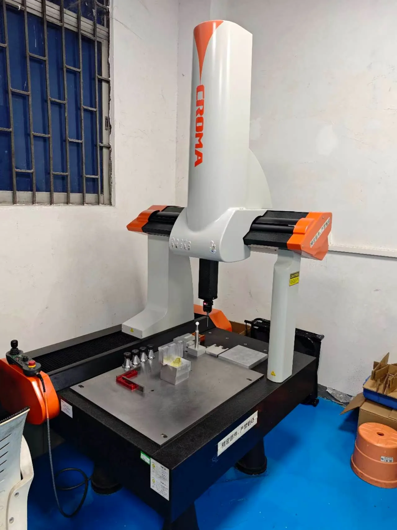
A coordinate measuring machine is valuable for complex geometry, positions, datum systems and multi-feature reports. The result depends on the program, probe strategy, alignment, number of points and interpretation of the drawing. A CMM is not automatically the best tool for every size measurement, but it is an important option when geometry and documentation require it.
VOGUC currently uses a 3D CMM, a 2.5D measurement system and digital height gauges as part of its inspection resources. The exact method is selected during project review.
What should be included in a full dimensional report?
A useful dimensional report should connect the drawing requirement to the measured result. Depending on the agreed format, it may include:
part name or controlled sample identifier;
drawing revision and production batch reference;
nominal dimension and upper/lower tolerance;
measured result for each sampled part;
minimum and maximum where multiple results are recorded;
measurement equipment or method code;
acceptance judgment and inspector approval;
date and traceability information appropriate to the project.
The sample available on VOGUC’s Quality page is sanitized: customer names, part identifiers and batch references have been replaced. It shows the type of structure that can be coordinated, not a universal promise that every order receives the same report without prior agreement.
Quotation checklist for a ±0.01 mm requirement
Before sending an RFQ, include:
A 3D CAD model and matching dimensioned drawing.
The drawing revision and unit system.
Material grade and material condition.
Quantity for prototypes and expected production batches.
Individually identified critical dimensions.
Datum and GD&T requirements where applicable.
Surface treatment, masking and post-finish dimensions.
Required inspection equipment or report format.
Assembly or application information that explains the function.
Packaging requirements for delicate or cosmetic features.
This information lets the supplier evaluate the complete process rather than quote a tolerance in isolation.
Frequently asked questions
Can every CNC machined dimension be held to ±0.01 mm?
No. Feasibility depends on part size, geometry, wall thickness, material, setup, tool access, finish and measurement method. Apply ±0.01 mm only where function requires it and confirm each critical feature during drawing review.
Is ±0.01 mm the same as high precision for every part?
It is a tight dimensional tolerance in many CNC applications, but precision is relative to feature size, geometry and process. Position, flatness, cylindricity or runout may matter more than a single bilateral size tolerance.
Does ISO 2768 guarantee ±0.01 mm?
No. ISO 2768 provides general tolerance classes for dimensions without individual callouts. The class and nominal dimension range determine the applicable limit. Critical ±0.01 mm requirements should be called out individually.
Should inspection happen before or after anodizing or plating?
That depends on the functional requirement. If coating changes the final fit, specify the post-finish dimension and masking requirements. Agree on the inspection stage before quotation.
Can VOGUC provide a CMM or full dimensional report?
Yes, when the report scope, characteristics, sample quantity and format are agreed before production. The required documentation should be included in the RFQ.
How fast can a tight-tolerance sample be produced?
VOGUC can complete some samples in as fast as three days after technical review, but tight tolerances, special material, finishing and inspection can extend the schedule. The confirmed lead time is project-specific.
Conclusion
The best tolerance is the one that protects function while leaving the supplier enough process margin to manufacture consistently. A blanket ±0.01 mm note can increase price and risk without improving the product. A clear drawing with functional datums, selective critical tolerances, finishing requirements and an agreed inspection plan creates a better result.
VOGUC reviews each CNC machining enquiry against geometry, material, quantity and evidence requirements. The goal is not to advertise the smallest number; it is to establish a process that can be quoted, manufactured, inspected and shipped with a shared understanding of acceptance.
Final CTA — Get a Quote: Send your CAD model, 2D drawing and marked critical dimensions. Ask for a tolerance and inspection review before ordering, and specify whether you need a CMM report, full dimensional report or material certificate.
Turn the tolerance review into an RFQ checklist
Download the CNC tolerance and inspection planning workbook to record critical dimensions, general tolerances and required inspection evidence.
Technical References
These official references support terminology and general planning context. They do not establish project-specific manufacturability, inspection acceptance or VOGUC capability.